nation
's Best
lamination
solutions
- POWER & DISTRIBUTION TRANSFORMERS

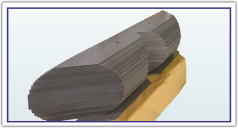
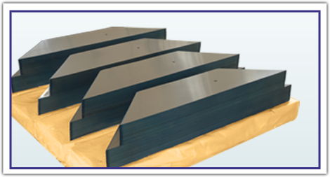
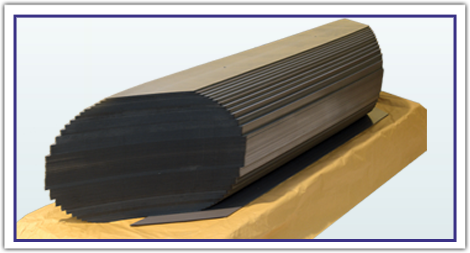
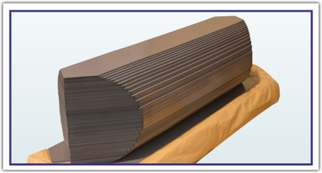
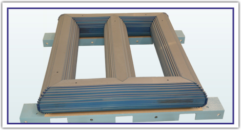
Transformer core lamination for power & distribution transformer is manufactured from various grades of cold rolled grain oriented steel. Lamination in various shapes & size are slit and cut to required accurate geometrical shapes with 90° & 45° angle cutting system.
As manufacturing of transformer lamination involves a high degree of precision engineering, we always strive hard for crucial quality checks of burr level, stack height, dimension and required weight.
- OVER LAP CORE AND STEP-LAP CORE:

Transformer lamination can be of various sizes for single or three-phase transformers, made with overlap joints or step-lap joints (Cross/Longitudinal). They are cut, punched and V-notched in order to fit in a particular transformer by CNC - cut to length line. Cutting, Punching and Notching of different shapes of sheets are possible in width up to 1000 mm and length up to 5500 mm.
VSPL, with its integrated software to convert conventional design to Step-lap design, insists transformer manufacturers to opt for Step-lap design. Step-lap core design enables easier path for flux to travel at the joints and therefore reducing No Load Losses of transformer core by 5 to 8%. Our Core experts are always ready to assists in core assembly if required.
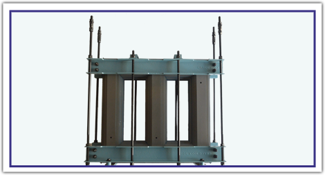
VSPL also offers excellent services in Lamination Assemblage as per the customer’s specifications for power and distribution transformers.
- LAMINATION QUALITY CHECK

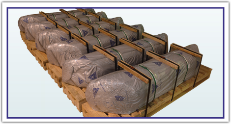
Lamination quality control checks are carried out frequently right through the starting of manufacturing process on machine to the dispatch. All the records are maintained separately for each drawing so the tracking of particular job can easily be available on our finger tips. As a final step of process, delivery inspector conducts the required inspections of Cut Lamination and releases it for the dispatch
- STANDARD TOLERANCE – cut core

Sr. No. |
Characteristics |
Acceptance Limit / Criteria |
1 |
Width (mm) |
0 to 100 (+/-0.15) |
2 |
Thickness (mm) |
±0.03mm |
3 |
Edge Burrs (Micron) |
Burrs Micron
10 |
4 |
Length (mm) |
Upto 350 (+0.00 / -0.30) |
5 |
Edge Camber |
For the material with a width greater than 150mm, edge camber shall not exceed 0.8mm for a length 1.5 meter |
6 |
Wave Factor |
For a material of width greater than 150mm the deviation from flatness expressed as a percentage shall not exceed 1.5% |
7 |
Angle |
+/- 5 Minutes |
8 |
Stack Thickness of individual stack expect centre step Unclamped |
+1 - 0 mm |

